Properly balanced hydronic heating systems have the potential to deliver a precise heating rate when and where it’s needed within a building. Without proper design and balancing, that potential rarely becomes reality. In the context of hydronics, balancing refers to the adjustment of valves to direct flow within a heating system, so that desired interior comfort levels are achieved and maintained in all areas served by the system.
Many systems use parallel circuits to deliver a fraction of the total system flow rate to individual zones within a building or individual heat emitters. Ideally, every zone or heat emitter in such systems would be identical to the others, delivering the same rate of heating with identical branch piping, requiring an equal percentage of the total system flow rate.
However, a more typical system will contain several different sizes or types of heat emitters, connected to the heat source. When this system is turned on, the flow rate that develops within each branch will be determined by the hydraulic resistance of that branch in comparison to the others, as well as the circulator used. The necessary rate of heat transfer to the heat emitter then may not be delivered. The system may be properly designed and installed, but without the follow up of proper balancing, its performance is likely to suffer.
Most hydronic heating professionals agree that balanced systems are desirable but opinions vary on what constitutes a balanced system. For the purposes of this article, a properly balanced hydronic system is one that consistently delivers the proper rate of heat transfer to each space served by the system. This definition may seem simplistic, but it reflects the fundamental goal of installing any heating system.
CONSEQUENCES OF IMBALANCED SYSTEMS
Without proper balancing hardware and adjustments, delivering the proper rate of heat transfer precisely when and where it’s needed within a building is almost never achieved. The most obvious consequence of an improperly balanced system is lack of comfort. This lack of comfort is usually attributed to room air temperatures that are too low, too high, or both.
Wide variations in interior temperature often lead to further problems. When some areas of a building cannot warm to the desired room air temperature, issues such as frozen piping, shrinkage cracks in wood and drywall surfaces, condensation on windows and the growth of mould and mildew can arise. Some other undesirable conditions that can result from improperly balanced systems include high flow velocities in piping components creating; noise and possible erosion, circulator issues including excessive energy, low efficiency or operation at high differential pressure which increases the potential for thrust damage of bushings or bearings.
FINDING A SOLUTION
To overcome these problems, it is normal practice to install various balancing devices. These include static balancing valves and dynamic balancing valves. System designers calculate the flow rate required to each terminal unit and select the type and size of the balancing valve to control the flow, based on the type of pumping system utilised, whether constant or variable speed. Variable speed pumps are more common because of their ability to vary the flow rate to meet demand. This reduces flow rates around the system, system heat losses and pumping costs; therefore, increases system delta-T and system efficiency.
Some balancing device options include:
- Static Balancing Valves or Manual Balancing Valves. These are suitable for use in constant flow rate circuits frequently in conjunction with 3-port valves or downstream of the differential pressure control valves in variable volume systems.
- Dynamic balancing valves Include Constant Flow Regulators, Differential Pressure Control Valves (DPCVs) and Pressure Independent Control Valves (PICVs).
- Constant flow regulators are modern automatic devices which respond to changes in differential pressure to maintain the design flow rate of the internal flow regulating cartridge.
- DPCVs are adjustable and respond to changes in differential pressure automatically, adjusting to maintain a stable differential pressure between the capillary insertion point and the valve body.
- PICVs control differential pressure across themselves, allowing a stable flow rate to be set on the valve regardless of any differential pressure changes upstream of the valve. The addition of a control head allows the valve to become the terminal unit control valve.
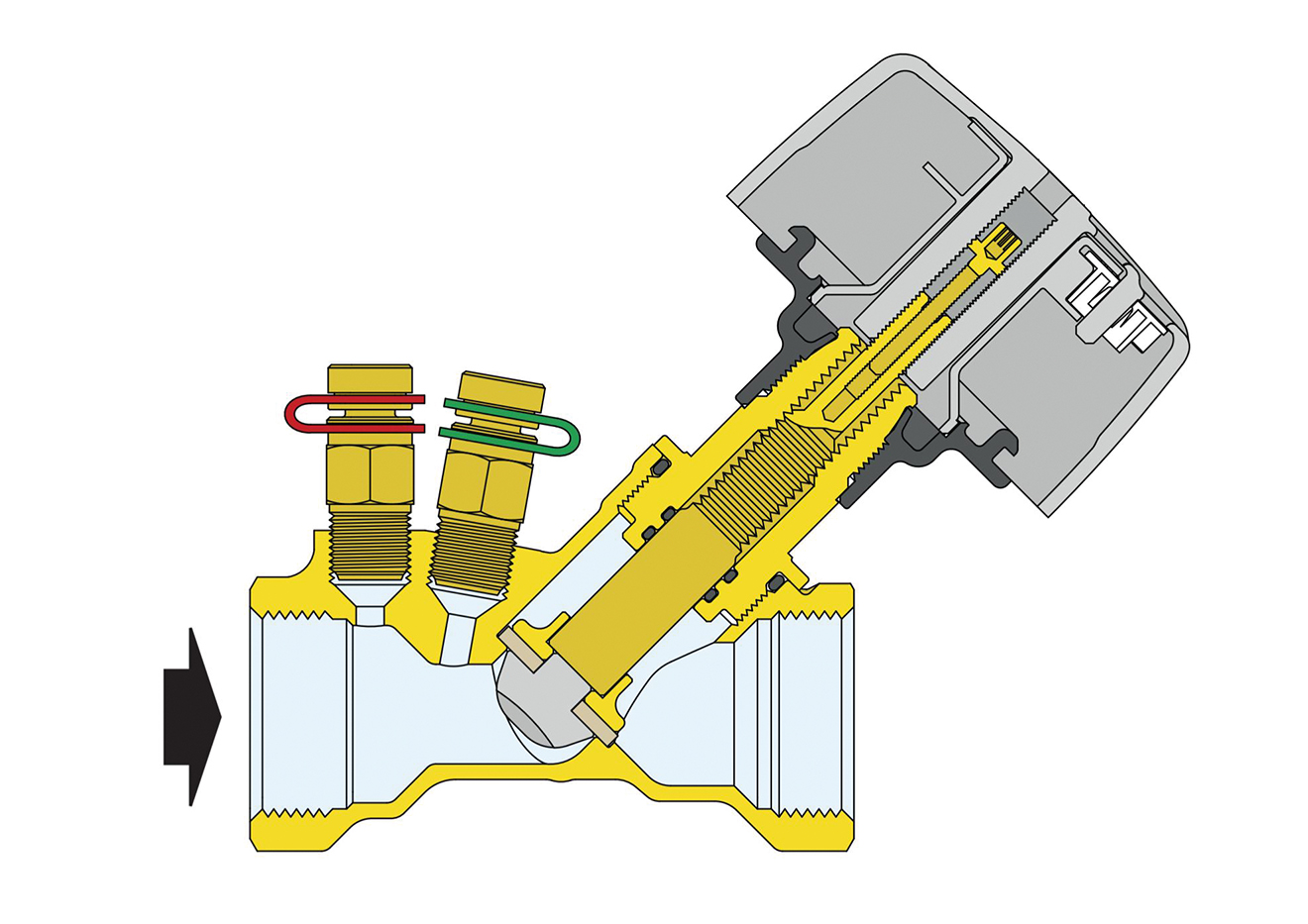
Pictured is the Altecnic 130 Series manual balancing valve – a Fixed Orifice Double Regulating Valve (FODRV) which uses a venturi to measure the flow of liquid passing through the valve. The venturi is located upstream of the double regulating valve, which provides stable flow measurement during flow regulation, making the valve quieter.
As shown in Figure 1, regulation is performed using a knob that governs the movement of an obturator, to regulate the flow of the medium. The flow rate is controlled according to the value of ∆p that is measured with two piezometric connections suitably positioned on the valve.
For more information, contact Chris Reilly, Country Manager for Ireland, on 00353 85 2152288 or e-mail chris.reilly@altecnic.co.uk or Gary Swann, Northern Ireland Sales Manager on 07760 596727 or e-mail gary.swann@altecnic.co.uk or visit the website at www.altecnic.co.uk